
I needed a pair of microphones for my master thesis. The same pair that was developed served me quite nicely over the years to perform also live music recordings. Below is a recipe for the most simple electret capsule microphones (ECM) on the planet with respect to component count in the signal path. That’s properly detached since electret microphone capsules generally deliver inferior sound quality (compared to condenser mics). So why make an effort?
An electret microphone is essentially a capacitor with one electrode that can move and acts as a membrane. Using constant charge in the electret material attached to the stationary electrode results in small voltage change across the device terminals every time the other electrode moves due to the corresponding changes in capacity. In other words it is probably the simplest microphone you could think of, right after that plastic cups connected by a wire thing you built when you were a child (you did not? It’s never too late). The ECM capacitor has high electrical impedance so it’s usually accompanied with an internal FET that buffers the pressure sensor from the load presented by the readout circuitry which could impede the membrane freedom to move and affect the sensitivity or frequency response of the sensor otherwise. As a result the capsule does require some external power supply, but that’s usually only a few volts and less than 1mA, nothing a battery pack can’t handle. This is the major benefit compared to the professional condenser microphone that requires tenths of volts for polarization which is way more difficult to power up (although it has the benefit of electrocuting singers who spit into the microphone too much).
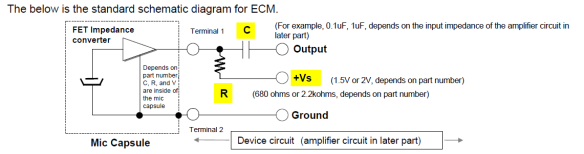
Below is the application note of the manufacturer that indicates how to supply the power to the ECM. (later on we’re going to dislike it and ignore the application note altogether, as any sane, detached engineer would):
In this project I used the good, old Panasonic WM61 ECM (WM61 datasheet).
ECM Parameters below:
Sensitivity 35 +/- 4dB (0db = 1V=Pa; 1kHz)
Output impedance: 2.2kΩ
Directivity: omni
Bandwidth: 20 – 20000Hz
Max supply voltage: 10V
Typ. supply voltage: 2V
Minimal recommended output load impedance: 22kΩ
Max current consumption: 0:5mA
SNR: > 62dB (non weighted!, when registering.1Pa signals (94dB))
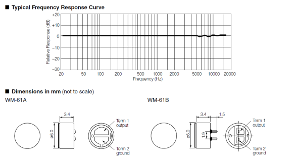
Like no other, this capsule offers some of the best noise performance (among electrets) and a flat, wide response, even below 50Hz (even if that super flat response in the datasheet is slightly over-optimistic). Unfortunately its production had been discontinued and the capsules are not available on Digi-Key anymore. This was announced back in 2013.
If you know a good replacement for the discontinued WM61 that offers similar or better specs let me know in the comments. Thanks!
The problem
In theory there are two basic ways to realize a simple voltage amplifier for the microphone using an operational amplifier IC:
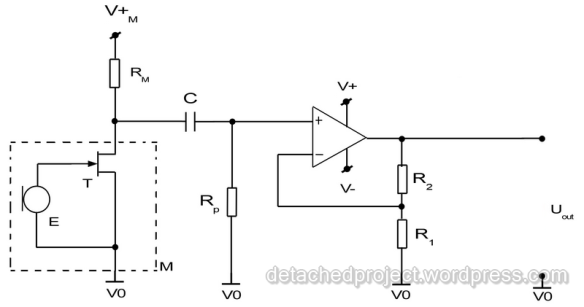
using a non-inverting topology:
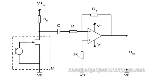
or using an inverting topology:
In both cases the DC supply of the ECM forces the use of a capacitor C in the signal path. In case of the non-inverting topology this in turn forces the use of the input ground return resistor Rp which is necessary to have the op-amp input work at all. (I was truly heart broken to learn that an AC coupled non inverting input of an op-amp can’t function. After all the years they tell you at school it’s ok to assume the op-amp is an ideal device this was like saying there really is no Santa). Going back to Rp, together with C, it forms a passive RC filter, which, as every passive filter, presents a load to its input (the capsule). So 2 components extra in the signal path and additionally to put the filter cut-off below 20Hz one has to choose a fairly large capacitor to start with.
In case of the inverting topology the input impedance (equal, roughly to R1) is usually less than what is required by the capsule manufacturer (22kΩ) to ensure the sensitivity of the capsule stays intact. This is the case when high gains are required anyway, that is when we want to use a large R2 and much smaller R1.
As an alternative, together with my promoter we’ve conceived something like this:

The difference in this case is that the reference of the capsule is set to –V and an additional feedback loop exists with an integrating amp that will ensure the capsule is powered up in such a way that the non inverting amp input DC level will always be kept exactly between V+ and V-. As a result we gain the following advantages:
- The signal path is as simple as possible, with only the non-inverting op-amp for signal gain. No passive RC filter on the input.
- The impedance seen by the electret capsule is maximal (non-inverting op-amp input), while there exists a DC path for the op-amp input return through the capsule.
- No DC drifts over time or temperature since they will all be countered by the low frequency negative feedback loop realized by the integrating op-amp.
- The system is readily acting as a simple, active pass-band filter with high-pass realized by the integrating amp in the loop, and low-pass realized by the Cm cap.
- If a low output impedance op-amp is used (typically found in op-amps with high unity gain) the circuit output can readily drive a simple, multiplexed single ended ADC input with minimum crosstalk.
The following govern the gain and the -3dB cutoff frequencies of the circuit (approximately!):
(eq1) Gain: K=R2/R1+1
(eq2) Lower cut-off: fcut Lo = K/(2πRiCi)
(eq3) Higher cut-off: fcut Hi =1/(2πR2Cm)
From the gain equations we can see that the only, somewhat negative, side of the system, and an unusual property, is that the lower cut-off frequency depends on the selected gain. Looking at eq.2 that also means that very high gain settings will force you to use large Ci (up to few µF) in order to achieve cutoff below 20Hz while using a decent Ri value (not too large). Generally however, it is a really good feature to have that lower cut off in place since the 1/f noise and very low frequency signals generated by air drafts are a big annoyance when recording. Fortunately, with the sensitivity of WM61 capsule I found a gain of just 22 to be sufficient in settings where the microphones are positioned relatively close to the instruments while running off a +/- 3V supply (when powering off four AA batteries – enough to last for many, many hours, so AAA are also a viable option). It should also be possible to run off just two batteries (+/-1/5V), however one should expect a slight decrease of the capsule sensitivity as a result (see datasheet).
Schematic of the practical circuit:
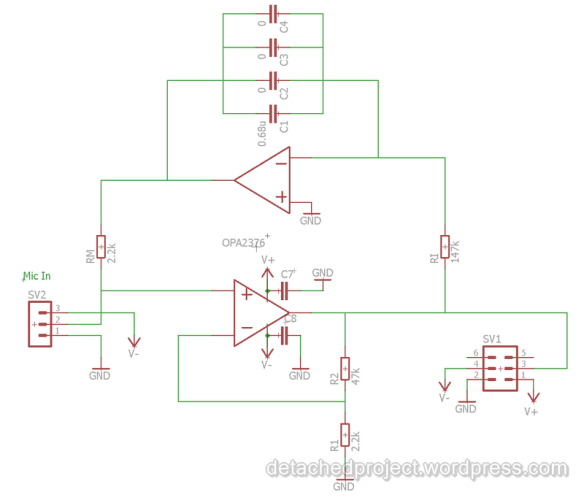
In this case the OPA376 amplifier was used due to its low output impedance, good current output capability (suitable to drive multiplexed ADC input with minimum crosstalk, and sufficient to deliver required supply current to the capsule) and good noise performance. Moreover, this amplifier was available in 2-amps per package which allowed to simplify the circuit layout with the use of a single, 8 pin MSOP package (OPA2376). Last but not lest OPA376 is a real rail-to-rail amp ensuring that we can achieve the best dynamic range possible with respect to the voltage supply provided. (BTW if you look well in the datasheet TI went detached as well, introducing an example application making an ECM compatible with professional consoles input with phantom powering, effectively turning the ECM output fully differential! There actually exist ECM based microphones (based on this same capsule) that make use of this approach)
The parallel connected capacities in the integrating amp are there just to leave some extra dummy footprints in order to be able to correct the lower cutoff frequency in case I’d ever wish to increase the amplifiers gain. Also note that the Cm is missing on the schematic which should be there to limit the output bandwidth to prevent aliasing if the next stage is directly an ADC input. With gain set to 22, adding a 150pF across R2, right underneath the PCB will do the trick somewhere around 20kHz. Remember that this will just realize a first order filter so the roll-off is slow. So if you can’t do considerable oversampling (e.g. 96kHz or more) you should seriously consider a proper active filter between the amplifier output and the ADC.
The PCB layout
Since the circuit is so simple I could fit all components (beside the IC) as through hole. This was also dictated by the cost since I wanted to build a matching pair of microphones (with carefully matching R and C value pairs in both channels), which demanded selecting the components from a handful of 1% metalized, low noise resistors and even larger handful of caps.
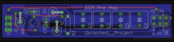
The PCB layout. Dimensions are 73.5mm x 16mm. The 0, middle potential on the input side is there just for testing.
The layout is straightforward. All thru-hole components are located at the top layer while the SMD amp IC is the only component at the back. The circuit could essentially be realized with only a single sided PCB.
This is how the ready amplifier PCB looks like:
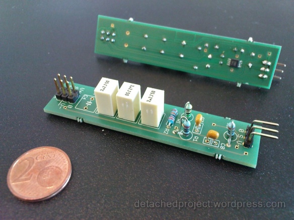
ECM amplifiers – the 3 large caps were used in a version with over 100x gain.
With all SMD components instead, one could probably fit within a fourth of this space to make a really miniature circuit, perhaps even sitting right behind the capsule.
Performance:
Here is a Ti-TINA SPICE simulation output for the circuit:
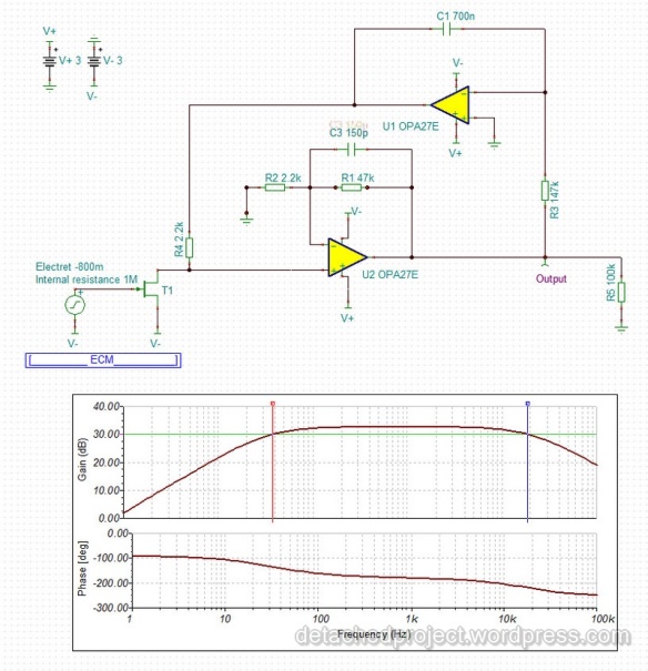
ECM aplifier circuit simulation in TI-TINA. NOTE: The indicated gain is higher than x22 because it is calculated between the electret input and the amplifier output, which includes the gain on the ECM internal T1 transistor.
The lower cutoff frequency is a little higher than the idealized equations above would indicate (eq.2). With Ci=0.7uF we get gain drop of 3dB already at about 36Hz. The difference results from TINA accurate representation of the OPA376 models (no idealization). The slow roll-off above 20kHz indicates the need for oversampling or an additional active filter before accurate ADC can be done at 48kHz or below. I used 125kHz sampling so that was just just fine for me.
The microphone enclosure
Below are some sketches in Auto CAD just to define the enclosure big enough to fit the pre-amp PCB with the largest Ci cap package. The Capsule is set off a little from the enclosure body with the flange in front to take full advantage of its small dimensions that prevent enclosure-sound wave interactions at high frequencies.


NOTE: the moment the enclosure comes in contact with the capsule body it is automatically connected to V-! Its easy to cause a short circuit by unintentionally placing the microphone on grounded metal surface.
The recording system:
In order to record music I used the same system as for measurement. After all, if you have measurement equipment accuracy ADC board, that means you also have a professional sound recording tool. The only limitation in this case was that I used an entry level measurement card (i.e. one I could still afford) which provides a 16bit depth with its ADC, and a multiplexed input. An ideal 24 bit, parallel Sample and Hold system would require one zero more on the bill.

On the other hand, considering the limited noise performance and existing recording standards 16bit is more than enough for the capabilities of the analog front end (the electret capsule). In terms of sampling rate the measurement cards usually do not support typical audio sampling but it’s not a problem to register a file at e.g. 125kHz per channel (even if we save to .wav format) and then down-sample using interpolation algorithms in audio software to e.g. 96kHz standard. In fact, what you can try is to down-sample a lot, e.g. to 48 kHz but to a 24bit depth format in order to recover some bit depth information in the interpolation process (best use the polynomial or cubic instead of linear approximation methods). This would be conceptually similar to what Philips tried by proposing 4x oversampled CD standard with only 14bit depth in each sample back in the times of the first CD players (the standard eventually lost to Sony’s 16bit, 44.1kHz format).
PERFORMANCE:
One of the few good things about living in Brussels is that it definitely gives you some good occasions to record music. There is a ton of street musicians, you can find music played live in shops with music instruments and there are groups playing at churches and chapels, and there is of course the Royal Conservatory.
Below is a sample selection from some nicer recordings made using this system at various occasions.
NOTE: All recordings were made in A-B microphones setup and at 125kHz sampling frequency per channel, and then down-sampled to 48kHz.
A piece from the Domming Porject performance of Duo Anonymus (link to their site) Performers: Pascal Ormancey, Thomas van Wetteren et.al.
A piece from the pre-release of the Polish Duo concert in China
Performers: Anna Kielecka and Natalia Brzewska
A piece from the pre-release of the Polish Duo concert in China
Performers: Natalia Brzewska
A practice session in a large concert hall of the Royal Conservatory in Brussels
Performers: Anna Kielecka
A practice session in our small room.
Performers: Anna Kielecka and Inez Popko
A sample of ensemble of instruments being tuned – room with low reverberation.
A sample of ensemble of instruments being tuned – reverberant conditions
In general, the microphones deliver sub-professional quality but its fair to say that the capsules punch way above their weight. Best results are achieved in close-miking setups (first 3 recordings). At larger distances from sources signal to noise becomes an issue and lack of clarity from limited micro-dynamics (somewhat muddled reverberation) are an evident weakness. All these issues are clearly audible in the 4th recording which was done at a greater distance in a very large concert hall. No wonder a lot of people go for close-miking these days. You can simply get away with worse equipment (and skills)! Nevertheless, in terms of balance and “instrument presence” the microphones do a surprisingly good job. For something like 10$ a capsule this is really way more than one should expect.
To sum it up these are quite some maxed-out electret microphones and prove that, given a chance, even a simple electret capsule can shine.
For measurement application the microphones offer flat response and can be a good basis for a matched pair in terms of gain and phase response because so few elements are involved in the signal path. I have been able to successfully deploy a matched pair in true sound intensity measurements (the so called P-P method).
For the future it would perhaps make sense to build a miniature, full SMD version of the amp PCB so that the batteries can fit in the same enclosure as the capsules.
Acknowledgements
Thanks to the musicians for their performances, thanks to REM-WAR for realizing the microphone enclosures and thanks to TI for the OPA2376 IC sample!
Take-aways
ECM Amp EAGLE schematic and board design:

Hi! Its design is a revolution in electret microphone polarization. Congratulations on the project, I’m really impressed. Could you give me a tip on how to do the same scheme for a 9v battery using the single source configuration? and also adding 3 more equal microphones?
LikeLike
Hello Stanislau. Thanks for the kind words. What you are asking for is one of the biggest pains of this circuit. It requires symmetrical power supply and a 4 core cabling (quite unusual). These are the two big pains you need to endure if you want to build one. This said, if you are ok with battery power I run my system off +/- 3V achieved with 4xAA battery pack powering both microphones. Cheers!
LikeLike
If you want to add the signals from more microphones you need to give each a separate amplifier and then hook these amplifiers outputs together into a summing amplifier circuit.
LikeLike
What a great expertise here!
To my opinion, now there is a newer, better replacement delivering a better S/N-ratio of +6 db.
The replacement for WM-61A is called POM-3535-L-2R, build by PUI-Audio, Inc, datasheet from Digi-Key.
I am very interrested in YOUR opinion about a replacement.
Thank you very much in advance !
– greetings from germany –
Wolfgang
LikeLike
Hi Wolfgang. Thank you. Apologies for late reply, its been ages since i posted this article that anyone is commenting 🙂 I just looked up the replacement capsule you mention and it looks very promising, even the noise figure looks considerably better than that of WM61-A (which is one of its greatest weakness for music recording) so this could be very good. The Freq. response rolls off quite sharp above 10kHz but then I’m not sure WM61 was that idealistic as datasheet says as well. I’d definitely give it a try, if that’s what you are planning. I still have a handful of these WM61 from some of the last stocks on RS, so its theoretically still possible for me to compare as well as with some more professional microphones, just not sure when I could find the time for this (kids).
PS: A bit off topic/boasting. These days I use some piece of software I wrote myself for quick spectrum tests you can find it here: https://github.com/mjablons1/twingo
Or if python is an issue for you, you can use ARTA software in demo mode (fully functional just no save/recall functionality, although quite a bit more complicated / capable than my tool). (https://artalabs.hr/)
Greetings from Poland
Michal
LikeLike
Hello again Michal!
Your answer has so promising to me to start a new try on new recording equipment (of this type). I am just a fingersnip away… but very honestly, I have some concerns to clarify first, before investing lots of time. THIS project is still state of the art, compared to other (i.g. simpler) designs – and I have been looking and working with microphones and preamps for decades now. Generally i do use Zoom digital recorder, mostly with external large-/small-diaphragm condensers. It serves my needs most often, but there are limitations. On my search for a very small recording hardware (goal: almost invisible/at least smalles shape for audience) I came to your design, just because of the newer/better capsules available now. As you know, capsules are the key issue, in combination with the pre-amp-design.
As an accordionist and technician (now more hobby), I do often recordings of soloists, groups, choirs most of them at churches. You might see the problem already: reflections, reverb, so called “terrible” area for good recordings, sure you know what I talk about, concerning post recording editing/mixing.
THE ISSUE IS THE CAPSULE…. the polar pattern is circle, NOT kidney or even better super kidney, what you will need to get to a promising recording (no matter if recording closer or with more distance). With circle pattern you will ALWAYS have this kind of trouble, more or less.
Now the big question around this all:
is there (do you know) a way to form a “kidney” oder “super kidney” pattern from such a small capsule with existing circle design? I know, it would be more a “mechanical” thing around it, giving it some kind of housing or damping inside… whatever… but with the goal to keep it as small as possible.
Have you ever experienced or do you know a solution for this problem ?
kind greetings
Wolfgang
LikeLike
Hello Wolfgang
I recognize your troubles and have gone through the same thought process. I had the same opinion till i got my hands on “Classical Recording A Practical Guide in the Decca Tradition” book. I read it front to end cover, pretty meticulously and that challenged some of my views, one being that omnis are evil because they pick up too much of the venue, too little of the target. With this book, you have to give it to them, its Decca guys and a few lifetimes of experience with gear and miking techniques all in one book. And they clearly claim on several occasion that Omni can be amazing, but you need great venue acoustics and amazing microphones that keep the circular pattern also on the trebles well. Also there is some extent of reverberant field boost in the trebles that the mics ship with or can be tuned to have (see here… https://www.dpamicrophones.com/DPA/media/DPA-Manual/4006A-Quick-Guide-DPI-4006A-QG-web.pdf?ext=.pdf) [ Ahh these will be mine, one day, just give me some time to become disgustingly rich… ). If you are not convinced by the book that omni does the job for classical check these miking experiments (http://soundmedia.jp/nuaudk/01Vn/index.html) (i love them I can spend hours listening to these). They are done with these DPA and Schoeps omins, some of the best pencil mics on this planet + top RMA interface.
Now, back to reality, lets say we don’t have 4000 Euro to spare for a pair of microphones and 3000 Euro for an RME interface.
Your ZOOM recorder is handy, so I’d keep it the way it is but how about equipping yourself with a pair of mics that can have the capsules attached to a special cable that allows you to put their amplifier parts somewhere further away (definitely less visible on the stage). The most reasonable pair I have found that has this is Neuman KK series, although it too is just electret. You can see that kind of cable introduced in this great video where this guy explains exactly your problem at 7:10 (https://youtu.be/twdqbH9FnKM). + amplifier its probably pretty expensive still. Well that depends on your budget.
Now if you really insist on tiny, you could redesign my project to an SMD one and shrink the PCB still. The symmetrical battery power will still be your enemy. 4x AAA battery pack is a pretty ugly thing, although i connect my batteries from a separate point down the cable so they don’t hake any of the “acoustical” space. I wanted to do the SMD version of these amps but I moved to equipping myself with off-the-shelf mics instead (my interest went from measuring to recording and I though that would do sound quality more justice.. well I’m still looking for a solution to this day)
Assuming your zoom can generate phantom power I’d use that power for the electret capsules you have in mind instead- i.e. build a more state of the art amplifier out of discrete transistors (should be still much better than my IC opamps). This is a very nice page (https://sound-au.com/articles/mic-electret.htm). I’m sure the project from that page will fit your needs much better.
Good luck and let me know of any progress!
Cheers!
LikeLike
You are great, Michal, really you are.
I will have to read all the sources you mentioned and yes, I will have to think over, because DECCA is known to me as well (and all the other ways, preferable ORTF and NOS), for a long time already. For sure, my Zoom H4n can deliver phantom power – so your proposal is not too far from reality. Anyways… THANKS A LOT to you. I really appreciate what you have done here, – and – your answers where you put a lot of time, energy and your personal konwledge in your writing too.
Good luck to you as well, what ever your future projects will be.
kind greetings
LikeLike